Testatika
| Previous chapter ( Resonant capacitors ) | Table of contents | Next chapter ( Vortical transformers ) |
Testatika is probably one of Tesla’s unpatented inventions. The existing models are the electricity sources for a religious community Methernitha in the Swiss municipality Linden. The machines of power at least 300 watts are shown on photo 1 and 2.
The main part of this machine is the grid-condensers in a shape of two large cylinders, the contents of which are said to be the inventor Paul Bauman does not show. The remaining parts make up the control circuit. The main part of this circuit is the Wimshurst electrostatic machine, which combines the generator and the engine. The remaining parts of the control circuit with their archaic appearance are related to technologies of the late XIX and early XX centuries, i.e. the times of Tesla.
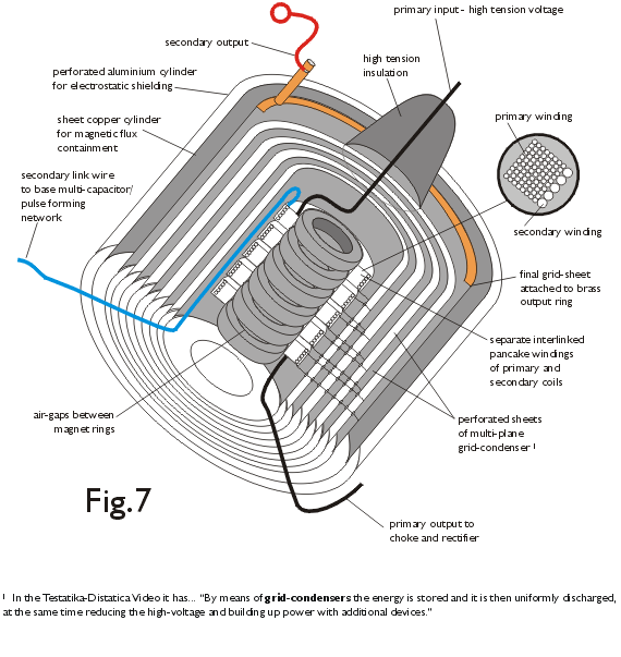
Internet (the print source is unknown), despite the secret of Paul Baumann, contains a figure of the grid-condenser, which clarifies all.

This device is a resonant capacitor, which utilizes the aetheric vortex energy and has the over-unity efficiency. It contains as few as possible dense solid components, so that the resistance to an aetheric vortex is reduced. The magnetic core is hollow inside, and it has the air-gaps, which divide it into the magnetic rings. The primary separated interlined windings are connected to a high tension insulation. The spiral shape of the primary pancake winding helps to form a vortex. The coaxial perforated cylinders form a single multi-plane air capacitor. The output ring is made of brass, because brass is used for the plug connections. The solid copper cylinder is inserted between the outer aluminum cylinder and the final grid sheet for the aetheric vortex (magnetic flux) containment.
A high voltage pulse in the primary winding produces an increase in magnetic flux and an induction voltage in the secondary winding, which charges the capacitor plates. The transverse vectors of the magnetic field and the capacitor electric field produce a circular aetheric flow.
The aetheric vortex receives an energy from the surrounding space, and gives it in a form of the induced EMF in both windings and a voltage on the capacitor plates.
The electrostatic machine does not produce the powerful magnetic fields due to a rotation of the electric charges, as someone think. It redistributes the charges due to the mechanical work so, that their total sum is zero as well as the average strength of a magnetic field. Also, the discs are made of nonmagnetic material. The lack of strong magnetic flux within the disks does not stimulate the aetheric vortices, which would produce energy.
The whole scheme is symmetric. Two grid condensers in this and in other designs are separated by a maximum distance to reduce their interference. The base capacitor means obviously a massive grounding, by which the aetheric vortices are trapped within the condensers by the electrostatic forces.
This schematic shows that the conventional transformers do not produce the DC output voltage, even if the electrostatic machine produces an energy.
The electrostatic machine has the standard electrodes: the collectors at the edges and the neutralizers between the opposite segments (not shown in the schematic). Four additional electrodes opposite to the neutralizing electrodes (two at each side) consist an electrostatic motor, which works only simultaneously with the voltage generation. The fifth additional electrode is the zero potential point.
Two pairs of the additional electrodes are connected via the current transformers so, that the voltage between them rises due to an induction in these transformers and decreases when the disks rotation work is done. The scheme shows these components too sketchy, but the photo 2 shows the visible wires.
The tube diode rectifies the voltage, which is applied to the electrostatic machine from the grid condensers. Its filament is powered by the AC voltage.
The operation begins after the wheels are launched by an external force. The collectors provide the pulsed high voltage, which is powering the condensers and the diode filament. After the diode warm-up, the pulses from the condenser primary windings produce the averagely unipolar pulses in the current transformers. In case of establishing the correct polarity of the electrostatic machine, the additional electrodes receive an average DC voltage, which moves the machine wheels. The correct polarity is established someway.
Upon reaching a sufficient power of the condenser vortices, an external force for the wheels rotation is not required. In this case, the machine is a self-oscillating system with a feedback. The positive feedback increases the wheels rotation frequency, and the negative feedback decreases it. The output voltage is proportional to a rotation frequency and to a frequency of pulses within the electrical circuit. The frequency response of this circuit provides a balance at a certain level, which is determined by the parameters of capacitors, choke-coils (called ECG), and an unknown element identified as ML2. The wheels as the flywheels suppress the system oscillations.
The machine should be easy stopped by stopping the wheels rotation, a power of which is much smaller than the whole system power.

|

|
| More powerful Testatika have additional condensers and the electrostatic machine of more high voltage. | Probably, the parallel condensers with the same field direction are arranged in the pairs. |
Something similar was invented by the American Lester J. Hendershot. The transformer combined with a cylindrical capacitor is used instead of the condensor. In the control circuit, the movable permanent magnet is used to start, and the movable armature is used to adjust. The output current is AC.
| Previous chapter ( Resonant capacitors ) | Table of contents | Next chapter ( Vortical transformers ) |


